GPS Guidance for Projectiles


Like any organization, the military constantly looks for ways to do more with less. More prolific use of "smart weapons" is one of them. As technology advances, smaller and smaller munitions become candidates for in-flight guidance. A prime example of this is the plan to use GPS guidance in Army artillery shells and in the projectiles fired from Navy deck guns. This presents a unique set of challenges, as the GPS receiver would have to meet the following requirements for in-flight guidance:
- 1. gun-hardening, to survive the gunfire shock
- 2. fast signal acquisition, to maximize the guidance interval
- 3. tightly coupled to an Inertial Measurement Unit (IMU), for jammer tolerance
- 4. based on Selective Availability Anti-Spoofing Module (SAASM), for battlefield security
- 5. interfaces and operating modes to support initialization of the GPS receiver
- 6. small size, to fit the allocated space
- 7. low power consumption
- 8. low recurring cost.
Projectile Firing Sequence
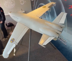
A typical projectile firing sequence illustrates some of the unique features needed in a projectile GPS receiver. The Army Excalibur 155-millimeter projectile (Figure 1) was designed specifically to be guided in-flight. The fins in the rear de-spin the projectile after firing, while the canards in front provide aerodynamic guidance control. Both are retracted into the projectile body before firing and deployed in-flight. The nosecone contains the guidance section, including the GPS receiver/IMU.
 Figure 1 Excalibur projectile |
Initialization. The projectile to be fired is removed from ammunition stores and placed into an initialization station (IS), which provides an interface to the projectile’s GPS receiver. The IS obtains data from two sources: an external "reference" or "gun" GPS receiver and the local mission fire control (targeting data). During the initialization process, the IS transfers GPS Time from the external reference GPS receiver to the projectile’s GPS receiver, which requires it for direct-Y acquisition. Additionally, the IS also provides to the GPS receiver
- 1. initialization power
- 2. broadcast precision ephemeris for all satellites presently in view
- 3. SAASM keys
- 4. the position of the gun from which the projectile is about to be fired
- 5. the coordinates of the intended target.
Next, the gun orientation and target information are transferred. The projectile is then removed from the initialization station. This removes Initialization Power from the projectile GPS receiver as time maintenance power is applied. The projectile is now on hold until it is loaded into the gun and fired and the signal acquisition process commences. This hold time (referred to as the time maintenance interval) can vary from a few seconds up to 20 minutes. During this interval, the projectile GPS receiver must maintain the initialization data set, the keys, and GPS Time. The receiver’s ability to accurately maintain GPS Time during this interval is determined by the frequency uncertainty of its reference oscillator.
 Figure 2 An epoxy serpentine underfill |
Acquisition. Once the projectile is fired, its main battery applies primary power to the projectile GPS receiver, which elaborates its software, executes a power-up self-test, and then reports "Ready to Acquire."
Upon receiving a "Start Acquisition" command, the projectile GPS receiver initiates a direct Y-code search for satellite signals. As soon as it has detected and acquired the signals from at least four satellites, the receiver outputs pseudo-range and delta-range measurements, aligns with the IMU, and begins to guide the projectile.
As the projectile leaves the gun barrel, it deploys tail fins which de-spin it through pitch control. It then deploys near the front canards controlled by a drive guidance unit which makes use of the navigation data derived by the GPS/IMU. GPS tracking continues until the munition dispenses or until jamming levels preclude GPS tracking.
 Figure 3 An epoxy dam |
Telemetry. During test firings, the projectile transmits telemetry back to ground monitor stations for performance evaluation. Operational rounds in the field, however, are completely passive – that is, they have no RF emitters. Having one would be dangerous since any RF emitter on a battlefield can be detected and targeted.
Gun Hardening
A major advantage of modern technology is the small size – and, therefore, low mass – of components such as application specific integrated circuits (ASICs). Also, ball grid array mounting of digital devices, with high input/output pin count, results in a dense, low-cost, and very strong component mount. Taken together with proper layout and packaging, many of the receiver components will survive gunfire shock without additional support.
Epoxy bonding is used where additional strength is needed. Figure 2 shows an epoxy serpentine underfill, which greatly increases the shear strength of the component mount. In some cases, the mounting will survive but the component is sheared from its base by the shock. Figure 3 shows the solution in that case: an epoxy dam to support the component.
Fast Acquisition
A projectile typically receives all its kinetic energy for flight from the gun charge. The muzzle velocity obtained limits the range and duration of the projectile’s flight. The projectile GPS receiver must acquire and track at least four GPS satellites for projectile guidance to commence. Clearly, the earlier in flight this occurs, the longer the interval available for guidance maneuvering. In addition, if jammers are present it is likely that they will be located downrange at or near the target. In that case, jamming levels will typically increase as the projectile approaches the target. Since acquisition requires a considerably higher signal-to-noise ratio (SNR) than tracking, it is important that acquisition occur as early in the flight as possible.
 Figure 4 The SAASM is packaged in a 1.5-inch square multi-chip module. |
Signal Search. The GPS signal search is a 2-dimensional process in time and frequency. The time search adjusts the condition of the local code generator to match the arrival code-state of the satellite signal, while the frequency search adjusts the frequency of the carrier numerically controlled oscillator to be at or near the carrier frequency of the satellite signal. This is necessary to provide a carrier phase reference (that is, a replica of the carrier phase and phase rate of the received satellite signal) in order to successfully phase-demodulate the Y-code from the satellite L1 carrier.
The demodulated code is then correlated with a local replica code. Note that since the Y-code has a period of 1 week, for direct Y-code acquisition the time search is not constrained to 1-millisecond, as is the case for C/A-code acquisition. This process also pre-positions the carrier loop for pull-in. The carrier loop is a variation of a phase locked loop known as a Costas loop. To acquire (phase lock), the loop’s operating frequency (provided by a numerically controlled oscillator) must be adjusted to match the actual frequency of the received satellite carrier. The acceptable error is about equal to the Costas loop bandwidth (less than 10 Hz typically).
Minimizing Search Time. All combinations of the total time uncertainty and the total frequency uncertainty must be searched to ensure that signal detection occurs. Acquisition search time is kept to a minimum in two ways – first by minimizing the range of uncertainties to be searched and second by maximizing the span of uncertainties searched in parallel by the receiver. The primary contribution that can be made by the receiver design to minimize the range of uncertainties to search is to minimize the frequency uncertainty of the receiver’s reference oscillator. This reduces both the time and frequency uncertainty to be searched. One of the largest contributors to this uncertainty is the oscillator frequency shift that occurs with gunfire setback shock. We have developed proprietary procedures and characterization data to minimize the uncertainty and a proprietary acquisition correlator design to define the parallel search spans.
 Figure 5 ERGM projectile GPS receiver CCA |
Frequency Uncertainty. The two main contributors to frequency uncertainty at acquisition are the projectile’s velocity (carrier Doppler) uncertainty and the frequency uncertainty of the receiver’s reference oscillator. The projectile velocity uncertainty is minimized by using all available information received during initialization including gun position, firing azimuth and elevation, expected muzzle velocity, drag, planned flight trajectory, and elapsed time since firing to estimate projectile velocity. A frequency calibration process for the receiver oscillator is a part of the initialization process to minimize its frequency uncertainty. This is necessary because the projectile may have been in storage for up to 20 years with no servicing. The calibration process removes the crystal aging effects. The calibration is done during initialization using the time intervals between the GPS Time marks that are also used to transfer GPS Time to the projectile. It is then only necessary to consider the oscillator drift during the hold period between initialization and start of acquisition and the oscillator frequency shift induced by the gunfire setback shock.
Time Uncertainty. The two main contributors to time uncertainty at acquisition are the projectile’s position uncertainty and the uncertainty of the receiver clock bias with respect to GPS Time. Projectile position uncertainty is kept to a minimum using the same methods as for projectile velocity. Usually the dominant part of time uncertainty at gunfire is the receiver clock bias uncertainty. The receiver clock is set to within 10 microseconds of GPS Time during initialization using the time marks as mentioned above. The receiver clock drifts at a rate determined by the actual receiver oscillator frequency error. The receiver clock uncertainty at start-of-acquisition is the product of the receiver oscillator frequency uncertainty and the time maintenance interval (up to 20 minutes). The frequency stability of the receiver oscillator over this interval is a major factor in minimizing acquisition time since it affects both time and frequency uncertainties. The primary contributor to oscillator drift is changes in temperature. The receiver is equipped with a temperature sensor. Sensed changes in temperature are used to compensate the time keeping for known oscillator drift characteristics.
Acquisition Correlator. The second part in minimizing acquisition time is to maximize the span of parallel time and frequency search embedded in the projectile GPS receiver. We had to trade off our desire for large parallel time and frequency search spans with recurring cost and power dissipation considerations. The resulting acquisition correlator in our projectile receiver will accept either an L1 or L2 input and operate on either C/A or P/Y-code. The search is centered on the best current estimate of the projectile position and velocity, and the receiver clock bias and oscillator frequency. The frequency (velocity) estimate generates code Doppler that minimizes correlation "smearing" over the long integration periods necessary for signal detection in a high jamming situation. The span of the acquisition correlator is sufficient to search the total time and frequency uncertainty boundaries for the first satellite to acquire in a specific jamming environment in less than eight seconds. This is sufficient to support a 14-second acquisition time (tracking four satellites delivering valid measurements) because the measurements from the first satellite acquired are used to reduce the time and frequency uncertainty boundaries that must be searched to acquire subsequent satellites.
Jammer Tolerance
The projectiles are typically equipped with a jammer nuller using multiple receiving antennas. The receiver must operate despite the residual jamming that makes it past the nuller. Our projectile receiver has a number of design features to improve its tolerance to jammers.
While GPS signals are below the receiver noise floor, the jammers are typically above it. The receiver must have sufficient dynamic range to accommodate this increased range of input signal levels.
The presence of a jammer has the effect of reducing the SNR in the receiver. To retain the best SNR, all the usual design considerations to minimize implementation loss must be observed. These are factors such as noise figure, filter losses, sampling losses, image rejection, and signal aliasing. The down conversion frequency plan must be free of in-band spurious responses.
Various parameters within the receiver can be adjusted to mitigate the presence of the jammer. Among these are the coherent and non-coherent detection integration intervals, the tracking loop bandwidths, and the signal sampling weights and spacing. However, the conditions of jamming must be known in order for these parameters to be optimally set. Our projectile GPS receiver is equipped with a jammer sensor suite whose output is the level and bandwidth of the jammer. These measurements are used to control the adjustable parameters of the receiver.
L2 operation is obtained in most GPS receivers by multiplexing the radio frequency down converter (RFDC) between L1 and L2 reception. However, any interruption of track in a high jamming environment is undesirable. L1/L2 signal multiplexing generates a SNR loss proportional to the dwell ratios with commensurate loss in tracking threshold. In addition, the interruption of track increases the likelihood of carrier cycle slip or drop lock. Therefore, the projectile receiver was designed with a separate L2 RFDC path. The L1 and L2 RFDCs both operate continuously without multiplexing. The selection of L1 or L2 operation is made at the input of each of the 12 separate satellite tracking channels.
Tightly-Coupled IMU
In a tightly-coupled inertial measurement unit (IMU), IMU measurements are used to rate-aid the GPS carrier and code tracking loops. This aiding removes most of the dynamic stress from the loops allowing them to operate in a narrower bandwidth than would otherwise be the case. This reduces the jammer and thermal noise power in the loop bandwidth, improving measurement accuracy and lowering the tracking drop-lock threshold.
The two main factors limiting the benefit of IMU aiding are the IMU measurement accuracy and the latency of the IMU data when it arrives at the tracking loop. The projectile’s IMU is not powered until after gunfire. It receives no transfer alignment during initialization because there is insufficient power available during the "time hold" period to sustain the IMU and because the dynamic range of the IMU is insufficient to track the 15-kilogram acceleration of gunfire. The IMU must depend on the GPS track to align it in flight. The IMU aiding becomes effective only after GPS has acquired and tracked over an interval sufficient to align the IMU. This makes early GPS acquisition all the more important.
Latency is minimized by converting the raw inertial sensor data – changes in velocity (DV’s) and changes in direction (DU’s) – to the satellite line-of-site range, range rate, and range acceleration. The latency is thus held to less than 20 milliseconds. This is adequate since the projectile flight does not contain any sudden high-amplitude dynamic events that would demand a shorter latency interval.
SAASM Security
The projectiles are tactical weapons that will be used on or near a battlefield. The projectile GPS receiver must be secure for this environment. A Selective Availability/Anti-Spoof Module (SAASM) is mandatory. Figure 4 shows the SAASM developed for this receiver.
The SAASM is packaged in a 40-millimeter (about 1.5 inches) square multi-chip module (MCM) using a laminate substrate. It is electrically attached to the receiver circuit card assembly by a ball grid array. A tamper-resistant coating covers the top of the module within a perimeter dam ring. This tamper-resistant coating is porous and so does not constitute a moisture barrier to the exposed die-form chips beneath it. An encapsulant and a moisture barrier are applied over the tamper-resistant coating.
All the digital GPS signal processing functions are embedded in the SAASM. The inputs to the SAASM are the sampled L1 and L2 satellite signals. The outputs from the SAASM are the satellite measurement set. The specific SAASM components are: the GPS ASIC containing 12 tracking channels each capable of tracking L1 or L2, C/A or P/Y-code; the acquisition correlator ASIC; a key data processor (KDP) chip set; and flash memory for signal processing program storage.
Fits the Allocated Space
The projectile GPS circuit card assembly (CCA) shown in Figure 5 is a typical outline to fit into the nosecone of a guided projectile. The projectile nosecone contains the initialization coupler, GPS antennas, the IMU, a guidance computer, batteries, and power regulators as well as the GPS receiver. Space was definitely at a premium. The projectile manufacturer defined the CCA outline and connectors to fit with the rest of these components. Note that the receiver’s reference oscillator and SAASM are visible in this view.
A metal shield covers the RF section, located on the far side of the CCA. The navigation processor and a field programmable gate array, used to customize the input/output interface, are also located on the far side of the CCA. The receiver interface with the guidance computer was kept as simple as possible. It consists of two serial busses, one for input and one for output, and several dedicated discrete lines.
Low Power Consumption
The requirement for low power conflicts directly with the need for large signal processing dynamic range and high sample rates demanded for jammer tolerance and for a wide-range search process for fast acquisition. The entire receiver is designed to operate from a single 3.3 VDC power source. The core logic in the digital ASICs is 0. 25-micron HCMOS operating at 2.5 VDC. These small geometry, low-voltage gates operate at considerably lower power than larger 5 VDC technology.
The receiver makes extensive use of "sleep" modes. Clocks are gated off when a process, such as a satellite tracking channel, is idle. The Acquisition ASIC enters a "sleep" mode except when an acquisition search is actually in progress. Each component in the design was selected with power consumption as the number two selection criteria (recurring cost being the first criteria).
Conclusions
The projectile GPS receiver has been designed to specifically address the needs of a projectile fire sequence and guidance. The basic design provides gun hardening, SAASM security, fast direct Y acquisition, jammer tolerance, low power consumption, and low recurring cost. These capabilities are mandatory for a projectile GPS receiver. Of course many of the features and performance of this receiver are desirable in any GPS receiver intended for military applications. The basic chip-set, the SAASM, and software that provide these capabilities can be used in a wide variety of applications.
For a glossary of terms and concepts used in this article, see page 30
Manufacturer
The Excaliber projectile uses the Tracker GPS ASIC and the Key Data Processor II chipset from L3-Interstate Electronics Corporation, Anaheim, California. The IMU incorporates a Micro Electro-Mechanical System (MEMS) produced by L3-IEC’s Micro Sciras group in Redmond, Washington. Further details on the system and the test methods used are described by Jeff Burd, of L3-IEC, in the paper "High-G Ruggedization Methods for Gun Projectile Electronics" presented at the Institute of Navigation’s 12th International Technical Meeting (ION GPS-99), in September 1999.


Subscribe to GPS World
If you enjoyed this article, subscribe to GPS World to receive more articles just like it.


Follow Us