GNSS on High


Gamma ray bursts, the most powerful explosions known, match the fury of a hundred exploding stars and appear to come from the far reaches of the universe. They occur randomly, last only a few seconds, and emit blasts of highly energetic gamma radiation. The key to understanding these extraordinary cosmic events lies in prompt followup observations in other wavelengths – optical and radio – from space and ground-based observatories. This requires good position information and millisecond timing accuracy.
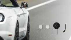
 White-painted GPS antenna on HETE2’s sun-pointed face. The phase centre of the two S-band antennas (TM and TC) that mask the GPS receiver is 11 centimetres from that of the GPS antenna. |
The High Energy Transient
Explorer (HETE2) satellite helps scientists study these mysterious cosmic phenomena by transmitting their location and exact time within seconds of detection to other observatories in space and on the ground. This article describes the use of GPS onboard HETE2 for satellite orbit determination and time-tagging the satellite’s sensor observations.
In 1992, NASA, MIT and CNES agreed to use a GPS receiver supplied by CNES onboard the HETE spacecraft. CNES delivered two receivers to MIT in December, 1993, and NASA launched the first HETE spacecraft in November, 1996. Unfortunately, the launch failed, but a second receiver went aboard the 110-kilogram HETE2 for an October, 2000 launch. The GPS receiver was powered on mid-October.
 Figure 2 Mode cycles during HETE2 orbit |
This article presents some of the first results obtained in orbit, when the HETE2 operations centre allowed downloads of only short measurements periods, giving higher priority to satellite health telemetry. Despite the few raw data available, we estimated the ionospheric delay using a code/carrier slip technique and produced a precise orbit on ground from these raw measurements. HETE2 achieved full operational status February 2, 2001 and now provides longer downloaded measurement periods.
The HETE GPS receiver was modified from a previous generation aviation receiver. The receiver on board HETE2 is equipped with the Determination Immediate d’Orbite par GPS Et Navigateur Embarqu���DIOGENE), a real-time orbital navigation software developed at CNES. An operational Kalman filter, DIOGENE can process most Earth orbits including circular or elliptic LEO orbits, Geostationary Transfer Orbits (GTO), and geostationary orbits. HETE2 also carries other software, computing position, velocity and time through an instantaneous least square resolution algorithm.
 Figure 3 Typical GPS operation plan along one orbit during the commissioning phase |
The DIOGENE state vector includes as a minimum the carrier spacecraft’s six equinoxial orbital parameters and the bias and drift of the receiver clock. It also accounts for orbital manoeuvres (and the associated uncertainty) and the solar pressure (which can be estimated by DIOGENE itself). Processed raw measurements are the pseudoranges and the pseudovelocities, if available (that is, not in “code-only tracking” mode). DIOGENE performs an orbital receiver autonomous integrity monitoring (RAIM). The receiver provides DIOGENE with corrected raw measurements, an associated quality factor, and the transmitter position. Thus, it can process any measurement coming from GPS, GLONASS, SBAS, GEOs, ground pseudolites, or other radionavigation references.
HETE2 is stabilised on three axes, and antisolar pointed toward the sky to observe during nighttime, that is, when the satellite is eclipsed by the Earth. The spacecraft has an equatorial, circular orbit with 2 degrees of inclination, an altitude close to 620 kilometres, and a 97-minute orbit period The GPS antenna has a sun-pointed semihemispherical pattern. This orientation allows some GPS signals to remain in the ionosphere for a long path, as shown in Figure 1.
 Figure 4 Control station map showing visibility circles for the 12 monitoring stations |
As the ionosphere presents a higher Total Electron Count (TEC) near the equatorial regions, we consider its influence on the GPS data coming from a single-frequency receiver is significant. For this reason, the operations centre can send a telecommand to the GPS receiver to set the altitude of a masking sphere centred on the Earth. This will improve the performances of the in-orbit positioning by removing from the navigation solution the measurements having the biggest ionospheric delays.
When we selected the receiver in 1992, cost and power consumption of available dual-frequency receivers formed a big constraint. Also, codeless techniques were not as well-developed at that time. As the W-code signal waveform is classified, it is difficult to use L1 and L2 codeless P-code pseudoranging for operational civilian applications in orbit, with no guarantee that the W-code structure will remain unchanged. Dual-frequency spaceborne receivers work well in science applications, but it is preferable to use only the C/A code to guarantee operational performance of the satellite platform. This is one reason, along with cost and power, why most operational spaceborne receivers, even on U.S. satellites, are single-frequency. Things will probably change soon because of the miniaturisation of the technologies, the additional planned civil signal on L2, and implementation of the proposed Galileo system by the European Council (EC) and the European Space Agency (ESA).
 Figure 5 C/No ratios observed on HETE2 |
Galileo’s Effects. Combined with the single-frequency method used with the HETE2 satellite to measure the ionospheric delay, classic dual-frequency techniques could improve global accuracy of the ionospheric corrections, and thus of the navigation solution. If Galileo signals are implemented, the wider their bandwidth in the upper L-band, the smaller the measurement errors due to multipath will be, and the better the separation between multipath and ionospheric measurement errors. This need for wideband dual frequency signals is particularly important for low dynamic applications, as in urban and/or indoor environments (in which multipath error appears as longterm bias), for pedestrians with cell phones or watches, fixed receivers for synchronisation and/or differential, and telematic applications.
Receiver Operations
HETE2’s receiver weighs one kilogram, has eight L1-C/A channels, and an anti-latchup device to detect damage from cosmic rays to current and memory, and to put the receiver in safe standby mode.
The GPS antenna is a low-cost, space-qualified L1 patch 96 millimetres in diameter, designed to minimise antenna pattern distortions due to the spacecraft structure. The satellite face housing the GPS antenna also carries several other pieces of equipment, including two solar sensors close to each side of the patch.
 Figure 6 Performance of the LSIR navigator |
The HETE2 GPS receiver can operate in a 0.5 watt low-power standby mode in addition to the operational mode 7-watt consumption. The GPS operational mode during each orbit is centred on the closest position to the sun (see Figure 2), while the standby mode takes effect during the remaining portion (the science sensors on the satellite’s anti-sun face continue to operate). This allows an acceptable average power per orbit consumption for the microsatellite. There is no need to activate the GPS on the night side, as the antenna sees mostly to Earth.
The receiver carries two orbital navigators running in real time onboard:
- 1. the Least Square Instantaneous Resolution (LSIR) filter, a calculation with broadcast ephemeris and pseudoranges, requiring at least four tracked GPS satellites for a nominal resolution.
- 2. DIOGENE, performing a hybrid action between orbital force model propagation and raw GNSS measurements in a Kalman filter. Post-processing on the ground consists in determining a precise reference orbit by removing the ionospheric errors and the GPS ephemerides errors through the use of IGS data. This precise orbit is used as a reference to measure the accuracy of the onboard LSIR and DIOGENE filters, running in parallel.
 Figure 7 Performance of the DIOGENE navigator. For both, Tdata 525 minutes |
A small quartz oscillator, consuming much less than the Thermal Controlled Crystal Oscillator (TCXO), maintains GPS time in standby mode. Random access memory (RAM) powered in standby mode stores the recent almanac and orbit parameters known before the last standby mode. When the receiver returns to operations from standby mode, DIOGENE quickly extrapolates its state vector to the current date, using a precise force model (40th order earth potential, sun and moon gravity, solar pressure), then it provides pseudovelocity aidings, allowing a reacquisition of visible satellites in about two minutes.
During the satellite’s initial operation phase (October 2000-February 2001), cold start tests were made, with 60-minute operational mode periods (Top). The program performed 30 cold start tests, all successful, with a time to first fix (TTFF) between 7 and 43 minutes.
Table 1 and Table 2 |
For operational use, both Top and data downloading period (Tdata) equalled 15 minutes, and the satellite successfully recovered operational mode from standby mode in every case. Average power consumption was 1.5 Watts, an acceptable value as a microsatellite’s limited solar panels deliver limited total power.
For orbit determination trial sessions conducted during ten days in November, Top was 60 minutes, while Tdata was about 25 minutes, with some missing Tdata periods due to TM traffic. These sessions produced the first set of results presented here. Figure 3 shows typical GPS operations during one orbit.
 Figure 8 Ionospheric delays measured onboard HETE2 |
In February, 2001 HETE2 completed in-orbit commissioning, with a complete check of the power consumption margins, and entered full operational status. We now follow these mission guidelines:
- 1. For operational use, Top and Tdata are 30 minutes each. The power margins allow an average power consumption of 2.1 W per orbit, still a favourable level for microsatellite operational use.
- 2. For orbit determination sessions, Top and Tdata will be at least 60 minutes. GPS data have a higher priority during these sessions than during operational use.
Onboard Performance
Another real-time screen in the operations centre shows the GPS priority telemetry status and carrier to noise (C/No) spectral density ratios. The average one sigma standard deviation of the pseudoranges measured on board is close to 2 meters. This is consistent with the C/No measurements as presented in Figure 5. This also illustrates that when the GPS antenna is not masked by the earth, the receiver’s eight channels are all in tracking mode most of the time.
 Figure 9 Ionospheric delays versus elevation |
The HETE2 reference orbit used to evaluate onboard navigation performances is computed only from the onboard GPS carrier phase and pseudorange measurements. An ionospheric correction to minimise GPS signal propagation effects, described in the next section, is done to compute this orbit. The standard deviation of the position solution residuals of this orbit is about 2.5 meters.
Both navigators present similar performances, with an advantage to DIOGENE, as shown in Table 1 and Figure 6 for the LSIR navigator, and Table 2 and Figure 7 for DIOGENE. The main source of error is the ionospheric delay, which is not processed by the current version of DIOGENE. The ionosphere had a larger than expected influence. In addition, for the HETE2 orbit determination trial session, GPS raw data are mostly available at the end of the GPS navigation mode, that is during the afternoon (local time), just before the orbit of HETE2 goes into the night, when the ionospheric delay is maximum. Due to the configuration of the ionosphere, HETE2 and the GPS satellites, it can be explained why the ionosphere errors appear along track and radial axes, and not along the cross-track axis.
Ionospheric Impact
The ionospheric delay can be evaluated from the code-carrier coherence of a single frequency spread spectrum signal. When phase measurements are available, the equations to use are:
p1 5 p 1 e
l1 (L1 1 N1) 5 p 2 e
with:
p15 code phase measurement (meters)
l1L15 carrier phase measurement (meters)
L15 number of cycles in the carrier phase measurement
l15 wavelength
N15 ambiguity of the carrier phase measurement (cycles)
p 5 pseudo-range without ionospheric delay (including clock and geometrical errors among others ) e 5 ionospheric delay in meters.
The single-frequency HETE2 receiver does not directly provide the ionosphere-free carrier-phase differences, which were reconstructed from the Doppler measurements – the carrier phase increment on the last second before the measurement time of the onboard receiver. (The satellite orbits at a velocity of 8 kilometres per second.) For the orbit determination trial session, measurements were performed every five seconds.
 Figure 10 Correlation between ionospheric delays and altitude |
By making the time difference of the above equations between the measurement time t and the date with t2dt with dt equalling one second, we have:
p1(t)2p1(t2dt) 5 dp 1 de
l1D1(t) 5 dp 2 de
with D1(t) the Doppler measurement in cycles.
Thus, we have an estimation of the ionospheric delay increment during dt. When the value of p1(t2dt) is unknown, it is reconstructed by interpolation of the p1 measurements.
The measurements have been performed every five seconds in onboard time (onboard clock in free drift) during the orbit determination trial session. For each GPS SV, the measurements include the time of transmission and the phase measurement over one second, and one estimation of the reception GPS time.
For each time period, the value of the code increment corresponding to the Doppler measurement is computed. Thus, we obtain the values of the ionospheric increments over one second, every five seconds.
These values can thus be integrated to give the ionospheric delay with an unknown bias (a rigorously constant error). Figure 8 shows the ionospheric delays obtained for a set of passes during one day (day 310, year 2000, in IGS notation 3100.00). As these values contain an unknown bias, the results have been aligned to zero for the first measurement of each pass. During a pass, a variation of the ionospheric delay may produce variations in pseudorange errors greater than 100 meters. To have a better view of the characteristics of the ionospheric delay, we can study it as a function of the measurement elevation angle versus the local horizontal instead of a function of time. Figure 9 shows results obtained for all measurements of day 3020.00, as a function of the elevation angle of these measurements.
Here we kept only passes with complete measurements from an elevation angle greater than 45 degrees, aligned the ionospheric delay to zero at the minimal point. We observe an increase of the delay from 90 degrees to about 215 degrees, and then a diminution, for all the passes. The limitation due to the earth is about 225 degrees, and the observed maximum delays correspond to an equivalent subionospheric layer at an altitude of about 350 kilometres, as can be seen in Figure 10, showing the correlation between the delay and the altitude of an ionospheric layer tangent to the GPS-HETE line, for the negative elevation angles.
These results show that a part of the ionospheric delay can be corrected (typically for an elevation angle higher than 210 degrees). The difficulty is to find, for each pass, the constant bias to add to the ionospheric contribution computed here. This requires an adequate model, not available at this time. A simpler approach consists of looking for a function with a typical shape coherent with the observations (ionospheric delay as a function of the elevation angle, for instance). This correction can be applied a priori on the measurements, or used to estimate the correction bias to be applied on the ionospheric delay measured on the complete pass. Figure 11 shows residuals obtained on the position solution, without and with these corrections, for the same initial measurements. Each pass’s bias is evaluated by fitting the ionospheric correction obtained by the code and Doppler measurements for an elevation angle greater than 210 degrees on the identified function.
The corrections are thus computed for passes presenting measurements for elevation angles greater than 210 degrees; passes with all measurements below 210 degrees are eliminated. No other eliminations have been performed.
The standard deviation of the position solution residuals after ionospheric correction is close to 2.5 meters. The position solution computed on ground from the raw code and Doppler measurements, corrected from the ionospheric delays as described previously, is considered as the reference trajectory to evaluate the accuracy of the onboard solutions delivered by the LSIR and DIOGENE navigators.
Conclusion and Future Work
The GPS HETE2 mission has so far yielded these preliminary results:
- 1. successful cold starts, tracking and standby recovery modes
- 2. no detected GPS hardware failures
- 3. despite duty-cycling of DIOGENE along the orbit, good navigation performance even with high ionospheric delays
- 4. robustness of DIOGENE and LSIR
- 5. ionospheric tomography using C/A code/carrier divergence, with reconstruction from Doppler measurements
- 6. identification of the ionosphere as the main driver of positioning errors
- 7. successful operational use of GPS as a primary means for satellite location and timing functions.
Future work on HETE2 will focus on improving the observed navigation accuracy:
- 1. new orbit determination sessions, with a 2/3 duty cycle, as they are performed now with more raw data
- 2. on-ground precise orbit restitution with identification of the unknown ionospheric biases
- 3. optimisation of the onboard DIOGENE settings
- 4. optimisation of the masking sphere radius
- 5. checking raw measurement statistics
- 6. validation of CNES algorithms concerning attitude determination using C/No measurements.
Acknowledgments
Significant contributors to this project include Joel Dantepal, Annie Comps, Francois Laporte, Didier Couture, Catherine Melezan, and Jean-Paul Berthias, CNES/CST; David Lahouze and Fran���s Martel.
ESPACE; G. Crew and G. Ricker, MIT/CSR; and Christian Mehlen and Christian Valpard, Alcatel Space.
Manufacturers
CNES procured two TOPSTAR 300 GPS receivers for HETE from Alcatel Space, Valence, France. The TOPSTAR 3000 is a space-qualified new generation receiver based on the TOPSTAR 100 (used on ARD) and the TOPSTAR 300. Rayan (Dourdan, France) provided the GPS antenna. CNES (Toulouse, France) developed the DIOGENE real-time orbital
navigation software.


Subscribe to GPS World
If you enjoyed this article, subscribe to GPS World to receive more articles just like it.


Follow Us