Indoor GPS: The No-Chip Challenge


 |
An irresistible force is moving across our quiet landscape, a force that is expected to increase demand for GPS by over one hundredfold, from a few million to hundreds of millions of units per year. This force is the demand for location capability in cell phones, driven in the United States by the Federal Communications Commission (FCC) requirement that cell phones be able to identify their location automatically with GPS-like accuracy (see sidebar “FCC’s E911 Mandate”).
During 2000, total sales for four GPS manufacturers – Trimble, Garmin, SiRF, and Magellan – amounted to approximately two million units (based on unit sales reported in, or estimated from information contained in, public documents issued by these companies). The potential GPS market driven by the cell-phone demand, however, looks considerably different. According to an April 2001 Strategis Group report, “Handset Databank,” worldwide cellular handset sales in 2000 totaled 426.5 million. The same report projects that handset sales in 2005 will reach 715 million units.
This cell-phone market opportunity represents one of the primary drivers behind the search for a GPS receiver technology that goes beyond a single-chip solution to what could be called a “no-chip” solution. Such a solution would share functionality with elements of the wireless communications handset itself.
Successful adoption of GPS into cell phones requires that the technology meet new demands, including indoor operation, near-instantaneous time to first fix, and very low power consumption. Feedback from phone manufacturers suggests that incorporating GPS should add no more than $10 to the parts cost of a wireless handset.
 Figure 1 GPS “System on a chip” architecture. The orange-colored components are those parts marked for extinction if a dedicated CPU can be eliminated. |
Conventional wisdom holds that the natural evolution of GPS technology is moving toward a single-chip solution encompassing everything from the antenna connection to a formatted serial output stream. Emerging silicon technologies, allowing integration of RF and digital circuits, are reaching the point where a single chip, performing all the functions of a conventional GPS receiver, may soon be feasible. Although this represents a possible path to integration in cell phones, a single-chip GPS may not offer the best solution.
One significant issue is the relative immaturity of semiconductor processes for simultaneously implementing RF circuits and large blocks of digital signal processing. Because of this, nearly all commercial GPS manufacturers have focused their efforts on two-chip solutions: an RF chip and a digital system-on-a-chip encompassing the GPS baseband signal processing and an associated microprocessor.
Even as hybrid semiconductor technology matures, an integrated RF/digital GPS chip remains unattractive for cell phones for one straightforward reason. Cell phones today already contain highly integrated chips: typically a single RF chip for receive functions, and a single digital system-on-a-chip for all signal processing and computing functions.
To minimize the incremental cost of adding GPS functionality, chip manufacturers plan to integrate RF and digital functions for GPS into the existing chips that perform these functions for cellular signals. This “no-chip” GPS solution is the logical end game for this application.
 Figure 2 A receiver correlation peak is shown over the frequency/code search space. Entire frequency and code space is shown. |
In this article, we will discuss Global Locate’s architecture for a no-chip implementation, and the existing chips that represent an interim solution.
The Traditional Approach
Many manufacturers assume that a no-chip implementation of GPS will closely parallel the system-on-a-chip GPS baseband of today. That is, they envision integrating all of the components shown in Figure 1. However, the presence of a dedicated central processing unit (CPU) and its associated circuitry mean that GPS systems on a chip are unnecessarily complex.
Efforts to eliminate the dedicated CPU and incorporate the GPS software into a cell phone’s existing CPU have, however, been thwarted by the high CPU load and high interrupt rate associated with traditional GPS processing. The computational complexity and real-time nature of these functions are inherent to current GPS systems in which tracking loops, integration, and search sequencing are all managed in software. For a GPS signal to be acquired in the first place, and for the tracking loops to maintain lock on the signal, the software demands an interrupt rate from the CPU on the order of two kHz.
In the future, if the traditional architecture is not changed, GPS firmware loading will increase dramatically as signal processing complexity increases to provide more parallelism for faster integration and weak-signal processing. For this reason, the conventional GPS tracking receiver lends itself poorly to a shared processor implementation.
 Figure 3 Standard GPS receiver architecture |
The mission to optimize GPS for cellular applications led Global Locate to undertake a new architecture design that would be suitable for shared processor implementation while at the same time substantially increasing signal-processing capability. The new architecture achieves massive parallel correlation and long integration times in dedicated logic, relieving the processor of computationally intensive tasks. A “thin” driver – with modest memory usage and no real-time response requirements – manages hardware functions and resides in the wireless CPU.
Indoor GPS and A-GPS
As mentioned earlier, the GPS feature in cell phones must work indoors, posing two significant technical challenges. First, neither time nor signal strength exists to demodulate GPS navigation data from the satellites. Second, finding GPS signals in the traditional manner is impractical because, as we will explain in this section, the receiver cannot dwell for long enough at each search location in order to achieve the required sensitivity.
In order to detect highly attenuated GPS signals indoors, dwell times must be increased by two to three orders of magnitude. This is done using two primary techniques: assisted GPS (A-GPS) which provides additional information through a communications datalink and massively increasing the number of correlators available for acquiring the encoded GPS signals. Assisted-GPS provides half of the answer to indoor use of GPS for cell phones.
A Chinese proverb counsels us that “Success has many fathers; failure is an orphan.” So it is with A-GPS, which is claimed as an offspring by many. The earliest reference we have found, however, belongs to Ralph Taylor and Jim Sennott, who, in a 1981 U.S. patent application, proposed: “an acquisition-aiding signal generated by an earth-based station is relayed to user terminals. The aiding signal identifies satellites in view and includes Doppler prediction data as well as GPS satellite coordinates.”
 Figure 4 Indoor GPS, hardware processing approach |
In the Taylor system, the GPS receiver is relieved of the burden of searching out the satellite frequencies, demodulating satellite navigation data, and computing satellite coordinates, because this information is provided over a separate wireless link. Of course, in the cell phone environment, a separate wireless link is readily available. Over the last few years, cellular handset makers such as Ericsson, Motorola, Nokia, and Qualcomm cooperated in the adoption of standard formats for A-GPS information interchange. We now have A-GPS standards for GSM, CDMA, and US-TDMA wireless technologies.
Figure 2 shows why it is useful to receive Doppler prediction data that describes the frequency shifts created by the satellites’ motions. The figure illustrates a GPS signal residing in a two-dimensional search space with unknown frequency on one axis and unknown code delay on the other. Code delay is the offset between the receiver’s locally generated code and the received code from the satellite. (Code delay is also known as PN code phase and corresponds to the sub-millisecond portion of the satellite pseudorange.)
Traditionally, a GPS receiver acquires GPS signals by sequentially searching this space, dwelling for a millisecond at each point on the two-dimensional grid. The longer this “dwell time,” the greater the sensitivity of the receiver (See sidebar, “Signal Threshold vs. Dwell Time”). A Doppler estimate and a stable frequency reference allow the search space in frequency to be collapsed to just a single frequency. This helps, but a GPS C/A-code signal still contains 1,023 chips of possible code delay. Even with a single search frequency, the practical limit of dwell time for a sequentially searching receiver is just a few milliseconds – woefully inadequate for indoor signal detection.
In GPS-synchronized cellular systems such as IS-95 (CDMA), we can extend the aiding information to carry delay estimate information that further narrows the search window. However, GSM, TDMA, and W-CDMA cell phone systems lack GPS synchronization and delay estimate information is unavailable.
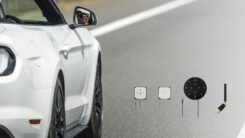
 Photos show some of the operating environments in which the authors tested a prototype receiver, including the urban canyons of downtown San Francisco (left) and inside an all-steel trunk of an automobile without back-seat access. |
To achieve high sensitivity in non-GPS��synchronized systems, the GPS receiver must be able to search a substantial number of delay bins in parallel. With enough correlators, all possible delays (that is, an entire convolution of 1,023 received code chips, and the same 1,023 locally generated code chips) can be calculated at once, and hundreds of milliseconds of convolutions can be integrated in real-time to provide the sensitivity required for indoor operation.
More Correlators, More sensitivity
The big payoff of having many correlators is vastly improved receiver performance. This can improve sensitivity and time-to-first-fix orders of magnitude beyond conventional receivers.
Figure 3 illustrates the implementation of a conventional GPS tracking receiver. The receiver has two modes of operation. During acquisition, a single correlator pair (or sometimes two correlator pairs) are used to sequentially search a range of delays. After acquisition, the receiver enters a tracking mode that uses feedback to maintain the correlators in the vicinity of the signal. The feedback process compares the energy in the early correlator to that in the late correlator. The receiver then adjusts the correlator offset to maintain the correlators at approximately the same distance on either side of the correlation peak.
While the signal is being tracked, sensitivity can be temporarily enhanced by increasing the averaging time in the delay locked loop. However, when the signal fades completely, the feedback cannot be maintained, and the signal will drift out of the range of code lock, necessitating a return to the signal acquisition phase. Thus, the overall system performance will ultimately always be set by the dwell time used for acquisition.
 A 16,000 Correlator Baseband Chip. Inset: same baseband chip and RF chip |
Figure 4 illustrates the implementation of a chip with more than 16,000 parallel hardware correlators. The large number of correlators is desirable to perform a complete convolution (that is, all possible correlation delays, at two samples per chip) in real time for many satellites in parallel without a sequential search. This obsoletes the need for separate acquisition and tracking stages. No matter what the actual code delay is, the output from the convolution processor will always contain the correlation peak and so a direct measurement of pseudorange can be made. In outdoor situations this means that signal acquisition occurs almost instantaneously. In indoor situations many seconds can be devoted to signal integration, which occurs in parallel for all delays.
More Correlators, Less CPU Load
The previous section illustrated the importance of parallel correlation for performance. Now we answer the question of how to provide this capability in the confines of a cellular phone. In particular, we address the effect that more correlators have on the CPU and whether a separate processor should be dedicated to the GPS function.
In a traditional GPS architecture, the processor has significant responsibility. The hardware typically ends in a set of registers containing correlation results for the past millisecond. The CPU must quickly read these registers. In a typical scheme, the CPU services interrupts at a steady 2 kHz rate, constantly checking all the hardware channels and processing any waiting results. In this scheme, the CPU load is driven by the need to read, store, and process correlation results in real time, and rises proportionally with the number of correlators in the design.
Having thousands of correlators would require an extremely high performance CPU. Furthermore, the interrupt-driven processing must run at high priority, making for difficult integration with other software tasks. For these reasons, the conventional architecture has characteristics that make it problematic for GPS software functions to be successfully hosted in an already busy wireless CPU, especially if the correlator count is to be increased.
Meeting the demands of massive correlation without a high-end CPU requires departing from existing architectures. The Global Locate architecture changes the division of responsibility within the GPS receiver, allocating increased functionality to hardware and greatly reducing the software role in signal tracking and processing. In this architecture, dedicated hardware handles all aspects of convolution processing and multisecond integration and also has features to provide frequency discrimination and data bit extraction from the GPS navigation message (when necessary), all without the need for rapid interrupts.
The hardware sends the results to the host CPU through a memory-mapped interface. In the CPU a non��real-time driver manages control of the correlation hardware and performs final GPS pseudorange processing.
More Correlators, Less Silicon
A design with thousands of correlators brings to mind issues of logic complexity and high gate count, and, if the standard GPS architecture were merely replicated, this would certainly arise. Fortunately, there are signal processing architectures for convolution that can be implemented efficiently in silicon. The Global Locate architecture packs more than 16,000 correlators with the associated long-term averaging logic into a compact digital correlation engine. Global Locate has developed a proprietary signal processing architecture that performs a large number of correlation operations in parallel, with relatively small logic complexity. As a result, the chip is very small and fits within an 838 millimeter package (see accompanying photo).
With the elimination of the dedicated CPU, the implementation requires less silicon than many conventional GPS systems-on-a-chip. Thus, we believe the architecture offers handset designers the ability to incorporate high-sensitivity GPS (even in asynchronous telephone networks requiring wide code-delay search ranges as described earlier) at a silicon cost that will prove to be lower than conventional outdoor GPS and without the data management complexity arising with an additional CPU.
The vision of many correlators operating in parallel also raises concerns with power consumption. Portable device designers want to prolong battery life and naturally pay close attention to the total energy required for each position fix produced. In terms of energy used, it turns out, perhaps surprisingly, that more correlators is a benefit rather than a liability. The reason is simply that a massively parallel receiver gets its job done more quickly than a receiver that applies a smaller number of correlators in sequence.
For example, consider an environment where detecting signals dictates a 50-millisecond dwell. A fully parallel receiver can perform all necessary correlations in real time, thus drawing power for a brief 50 milliseconds. A less powerful receiver, say one capable of searching 10 chips in parallel, requires 100 times as long (5 seconds). The fully parallel receiver, being 100 times faster, could draw up to 100 times more instantaneous power and still only require the same energy as a receiver that takes 100 times longer to process the signal. In practice we find the fully parallel receiver to be much more efficient.
RF Chip
In this article we touched only briefly on the subject of RF integration, noting that in the ultimate “no-chip” solution this function vanishes inside the cellular RF design. As an interim step, a stand-alone GPS RF chip must be as integrated as possible, ideally using no external components. State-of-the-art solutions can approach this today.
The Global Locate RF chip design incorporates an integrated low noise amplifier, integrated voltage controlled oscillator, and an integrated frequency synthesizer that works with any reference frequency without the need for an external phase lock loop. The only significant external component in this RF architecture is a surface acoustic wave (SAW) filter, a component that cannot be integrated in silicon, but is highly recommended to prevent jamming of the GPS receiver by the cell phone transmitter.
Test Results
In conjunction with third parties, we tested devices with the architecture described in this article in the following environments (portrayed in some of the accompanying photographs): outdoors; under trees; in downtown San Francisco; indoors in interior windowless rooms (in pants pocket and shirt pocket, in locked filing cabinets, and inside closed microwave ovens); inside closed elevators; inside the closed all-steel trunk of a car (while stationary, moving at 70 miles per hour, and inside a five-story covered parking garage).
In all these environments the devices successfully acquired satellites and calculated correct positions. In all but the first two environments (outdoors and under trees) commercially available, standard GPS receivers could not acquire satellites nor compute position. For the 16,000 correlator architecture, the time to first fix indoors is a few seconds; when outside, it is 100 milliseconds.
In conclusion, we have seen in theory and in practice that, for cell phones, the most desirable GPS architecture uses massively parallel hardware correlators and relies less on a CPU. This enables the GPS receiver to acquire very low strength signals indoors; when outdoors, the receiver can get a first fix extremely rapidly. All this can be achieved with less silicon than would be required using traditional GPS concepts and architectures.
;


Subscribe to GPS World
If you enjoyed this article, subscribe to GPS World to receive more articles just like it.


Follow Us