Real-Time GPS FX On-Screen Positioning of Racecars


 |
Special effects, or FX in video jargon, have long served as a mainstay of television broadcasting. Now a New York company specializing in enhancements for televised sports has incorporated GPS into its tool kit. The result? A system that tracks and displays on screen the real-time location of all cars during a racing event.
Television broadcasts increasingly use technology to enrich the experience of sporting events. Such technology, along with its associated graphics and statistics, not only entertains viewers but also enables them to gain insight into the performance of the athletes and, in the case of motor sports, their machines.
Founded in 1998 as a privately held company headquartered in New York City, Sportvision develops technology-based enhancements for the Internet, sports television, and new media platforms. Among its most recent innovations is RaceFX, a system that incorporates GPS and other technologies to enable real-time tracking and display of the location of all cars throughout a racing event. The custom GPS engineering described in this article was developed in conjunction with NovAtel Inc., a GPS technology supplier based in Calgary, Alberta, Canada.
RaceFX gives the broadcaster new tools to tell the story of the race and increase the enjoyment of racing fans. The National Association of Stock Car Automotive Racing (NASCAR) introduced RaceFX in television broadcasts at the Daytona 500 in February of this year. NASCAR uses the system to generate graphics, calculate speeds, and compute other performance-related parameters of interest to the racing fan.
 Figure 1 Screen captures of typical RaceFX graphics |
To achieve this capability, RaceFX uses compact, high-performance GPS receivers to provide real-time measurement of racecar positions. Coupled with other data inputs, the system generates graphical effects relevant to the current view of a race camera by directly coupling real-time vehicle positions to the broadcast screen images. Accomplishing this requires precise information of the target car’s position and how each pixel of the video display maps to the real-world coordinates of the track.
This article describes the design and development of RaceFX and its implementation in the challenging environment of high-speed racing dynamics.
The Flag Goes Down
Auto racing has traditionally used inductive sensors similar to automated traffic sensors in the track to measure lap times and speeds by detecting when a racecar crosses the start/finish line. Using high-accuracy GPS data, however, allows creation of "virtual" lines by defining positions along the track. Comparison of lap times using the GPS sensors and lap times measured with inductive sensors agrees to within 0.005 seconds. Virtual lines are used in the broadcast to show instantaneous speeds at arbitrary points on the track and average speed between points along the track, such as turns and straightaways.
Precisely locating a racecar in the video frame enables a variety of graphical enhancements. For example, a graphic could be created to point at a specific racecar. This graphic could show the name of the driver and related performance information, such as speed or time behind the leader (see Figure 1). This would help the viewer understand important aspects of the race more clearly. With knowledge of where every race car is at all times during the race, the system can generate rich statistical information, such as what racing "line" or path the fastest cars drive on the race track.
 Figure 2 The RaceFX sub-systems |
These performance objectives for RaceFX posed a complex set of challenges to system developers. Accurate vehicle positions needed to be obtained, calculated, and transmitted during a high-dynamic operations under racing conditions in which GPS satellite signals are frequently blocked or reflected (multipath). The derived positions then need to be interpolated and linked to screen images of the vehicles and their associated graphics in real-time.
System Description
The Sportvision RaceFX system consists of four subsystems (see Figure 2) GPS, telemetry, time synchronization, and video overlay. Each racecar has a GPS receiver and a 900 MHz transceiver. Mating 900 MHz transceivers are remotely located around the track and send data over DSL modems to the control center in the on-site television broadcast center where the communications controller, time synchronization, and video overlay system reside.
RaceFX employs a sophisticated telemetry system that transfers position and other vehicle information from all race vehicles to a central processor at the rate of five times per second. Differential GPS (DGPS) pseudorange and carrier phase tracking techniques generate vehicle coordinates accurate to 50 centimeters (1 sigma). The telemetry conveys differential messages from GPS base stations to the racecar rover units at 0.5 Hertz and racecar rover information to the video subsystem at 5 Hertz.
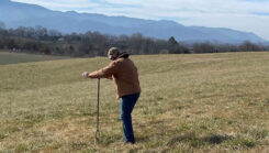
 A racetrack has numerous features that can obstruct satellite signals, as seen in the photo at top. |
RaceFX processes the five-Hertz DGPS positioning data to derive many useful parameters. The instantaneous position and time data are used to place a virtual object in the video stream. Because the data packet from each rover must be kept small, speed and heading are calculated from the computed velocity vector between sequential GPS positions. Lateral and along-track acceleration are also calculated using the velocity data.
Six broadcast cameras are instrumented to measure their pan, tilt, zoom, and focus 30 times per second or once per video frame. RaceFX interpolates racecar position information to correspond with the camera orientation in each video frame. High-speed computers combine this data to appropriately juxtapose the car and data in the video frame.
The video overlay accepts information from all rovers and reformats it for individual video frames of the particular camera used in the broadcast, while the time synchronization subsystem tags each video frame with a GPS time stamp. The racecars travel at speeds up to 90 meters/second. Relative timing between the video, and GPS must be accurate to one millisecond to keep time-induced errors below 10 centimeters. The GPS-based system maintains the timing to about 10 microseconds, or 100 times better than the minimum requirement.
 Figure 3 This color-coded map shows the number of GPS satellites visible on different portions of a NASCAR racetrack. |
A key element in RaceFX is the creation of an accurate digitized model of each racetrack. This model supports RaceFX’s video display of real-time data and is also used in the signal-processing method to improve the real-time positioning accuracy of the racecars. We will discuss the creation and use of these track models in a separate section.
GPS on Board
Tracking satellites and computing an accurate position in a racecar does stress a conventional GPS system. The greatest challenge to maintaining continuous, accurate GPS position fixes on a racetrack is obtaining visibility of the minimum number of GPS satellites required for position determination.
Although four satellites is the minimum number required for three-dimensional positioning, in a constrained environment such as a racetrack four satellites often do not have the necessary "geometry" to obtain the accuracy required for the RaceFX application. Satellite geometry translates into the so-called GPS dilution of position (DOP), which acts as a multiplier of the cumulative error generated by other factors, such as receiver electronics, ionospheric effects, and multipath.
A racing facility typically contains many buildings, fences, and, occasionally, walking bridges, which can block the GPS rover units’ view of the satellites. The accompanying photo of the Daytona facility illustrates some of these potential obstructions. Moreover, all tracks have a grandstand area and a wire fence around the outer edge of the racing surface.
Figure 4 Block diagram of racecar electronics |
Sportvision usually installs a GPS reference station for generating and transmitting differential corrections on top of the race track grandstands with a clear view of the sky. However, for vehicles operating on the track, the various obstructions frequently combine to reduce the number of visible satellites to as few as three with a poor DOP, thereby degrading the accuracy of the position data (see Figure 3). Furthermore, with lap times as short as 20 seconds, satellites are constantly coming into and going out of view of racecars during their circuits of the track, creating even more degradation in positioning accuracy and signal availability.
NovAtel and Sportvisionengineers have developed several techniques to minimize these shadowing effects by incorporating a computerized model of the track into filters that provide more precise positioning. The track model and filtering techniques will be discussed later in this article.
Another crucial aspect of this system is the design of the hardware components deployed in the race vehicles themselves. Racing conditions demand that the hardware in the rover units be extremely robust. For example, during the Winston cup race in Daytona in February, a multi-car accident occurred involving more than 20 cars, some of which were airborne and inverted. Although the accident severely damaged some vehicles, the cars’ electronics systems continued to function, including the GPS receiver, RF modem, and CPU.
 Marv White, Sportvision’s vice-president of engineering, checks monitor in RaceFX control center. |
Data, Hardware, and Communications
Another technique developed for RaceFX consists of generating a special message containing GPS satellite ephemerides generated at the GPS base station and transferring this data to the rovers via the differential datalink. The special ephemeris message is necessary because downloading the ephemeris message directly from the satellites would require 30 seconds of continuous coverage at the rover units, which could not be guaranteed under race conditions.
All racecars used by the 43 NASCAR teams have a Data Acquisition and Positioning System (DAPS) installed (See Figure 4). (In reality, each team has about 10 cars that are slightly different for use on the various NASCAR tracks: road courses, short tracks, and super-speedways. They take two cars to each race, one as a backup.) The DAPS contains a 12-channel, dual-frequency GPS receiver, a 900 MHz spread spectrum radio modem, a 486 computer, and some custom interface electronics.
The radio modem transmits GPS position information from the racecar to the base stations and receives GPS differential correction information from the base stations for the rover unit on the racecar. A single computer in the RaceFX control center, the communications controller, manages all of the data between the telemetry and GPS receiver and samples sensors attached to the racecar (RPM, throttle position, etc.). Batteries provide power to the system. The entire package is mounted to the racecar roll cage with vibration isolation mounts.
 Figure 5 A highly accurate vectorized digital terrain model is created for each track on which RaceFX is used. |
A high-performance vehicle, such as a NASCAR stock car or CART Champ car, experiences between 6 and 18 G’s of vibration on the chassis. At these vibration levels, the crystal oscillator in a GPS receiver will induce enough phase noise in the oscillator signal to create satellite tracking failures. To avoid this, the oscillator must be mechanically isolated from the vibrating car in order to reduce the vibration to below 3 G’s. As shown in the photo below, the entire racecar electronics package mounts to the car chassis using rubber isolation mounts.
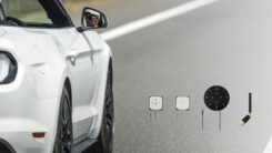
NASCAR regulatory authorities mandate that an electronics package cannot affect the aerodynamic or mechanical performance of racecars. Installing the GPS antenna without affecting the aerodynamics of a car traveling 200 mph and yet maintaining good satellite visibility required an innovative design.
The RaceFX installation employs a metallic "soap dish" containing the GPS antenna that fits under the car’s sheet metal roof. A hole cut in the roof and covered with a fiberglass plate forms an RF window. Once installed, the antenna is not visible from the outside of the car and does not affect the aerodynamics. However, this recessed design reduces the antenna gain for signals from GPS satellites at low angles.
 Figure 6 RaceFX planar grid is superimposed on photo of Fontana track |
Building and Using Track Models
A track model is a virtual set of planar surfaces that approximate the contiguous surface on which the race takes place. Typically, a NASCAR track can be accurately represented by a series of fewer than 3,000 contiguous triangles defining the planar surfaces of the track. (Each triangle is typically between 5 and 10 meters on a side). Once the GPS reference station-to-track model reconciliation takes place, every point or vertex on the triangles has a position accuracy of 10 centimeters or better (1 sigma), relative to the GPS base station.
To obtain this, a digital representation of the track surface is created using aerial photogrammetric techniques. High-resolution overlapping aerial photographs taken from approximately 300 meters above the track surface are processed by analytical photogrammetric workstations to create a digital terrain model of the track surface in the local state plane coordinate system. GPS survey receivers are used to obtain ground and camera control for the aerial photography process. Observable features such as paint on the asphalt, fences, walls, buildings, and pavement boundaries are captured as well. The relative accuracy of the track model itself is also within 10 centimeters (see Figure 5).
Figure 6 shows a conceptual representation of the planar sections defining the track model. The fence on the right side of the track plus the grandstand behind it contribute to the signal masking and signal degradation associated with this environment. We will address this problem in more detail later.
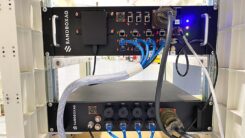
 A RaceFX electronics package on board |
Track Model to GPS Base Station Translation
Proper operation of the track model GPS software requires that the GPS reference station be located so as to enable removal of any offsets between the track model or aerial survey (based on state plane coordinates) and the GPS reference frame (based on WGS84). The GPS base station coordinates are initially determined from a time-averaged set of single point positions.
Once the GPS base station is installed, GPS positions for the features captured by the photogrammetry and represented in the track model are measured using real-time kinematic, carrier phase differential techniques. The longitude, latitude, and altitude position offsets between positions of features in the GPS base station frame and in the track model frame are computed for at least three locations. Once a consistent offset is established, the position the GPS base station uses to generate a differential reference is shifted so that the track model and the differentially corrected GPS positions are in agreement to within 10 centimeters.
A New Observable
The accurate three-dimensional model of the track with its contiguous triangles defining the planar surfaces provides an additional observable to the GPS position computations. RaceFX accomplishes this by determining the triangle "within" which a vehicle’s GPS antenna is at any moment. As mentioned earlier, each point on the triangle has an accuracy of 10 centimeters. These triangles comprise a planar position grid in which each grid covers an equal area of the track.
 Figure 6 Unaided GPS positions of antenna on test car at California Speedway, Fontana, California |
Based on the known, fixed distance between the GPS antenna and the ground in each vehicle, a planar constraint can be defined for each vehicle’s antenna with respect to the local planar section. As long as the vehicle operates on the track, the distance to the GPS antenna in a direction perpendicular to each triangle representing the track surface is known. This is quite similar to a height constraint. Once a vehicle is identified with an appropriate triangle, this information provides an observation equivalent to a very accurate additional satellite/receiver range.
RaceFX determines the correct triangle using the best available vehicle position calculation. This is derived from either the previous pseudorange position or the current epoch’s best pseudorange/carrier position, depending on which of two software filters the system is using at the time. Once a position is supplied, the GPS receiver transforms the position into the planar frame of the track model grid. The computer then conducts a sequential search through a linked list of triangles until it finds either the triangle that contains the supplied position, or it determines that none of the triangles contains the given position. When the computer finds a triangle, then it can use the information to generate an enhanced position.
 Figure 7 GPS positions of antenna on test car at California Speedway, Fontana, California, incorporating track-model constraints |
The track model is incorporated into either a least squares pseudorange filter or a Kalman filter that generates RTK carrier ambiguities to provide a constraint for more precise position determination. See the sidebar, "Two Filters and a Track Model."
The effects of the track model constraints are twofold: they significantly improve position accuracy prior to ambiguity resolution and substantially shorten the time to fixed ambiguity resolution. Taken together, these constraints typically allow the GPS receiver in the vehicle to generate positions on the racetrack with a resultant error of less than 0.5 meters.
Testing the System
Figures 6 and 7 quantify the improvement in height position repeatability in a test performed at the California Speedway Fontana track in February 2001. The plots show height versus longitude computed without and with the track model constraints, respectively. This data was generated by completing 17 circuits of the Fontana track, using a distinct break in the pavement between two strips of asphalt as a guide. We had no external control against which to measure positioning accuracy; so, we drove around the track a number of times following the pavement break and then looked at the system’s repeatability to see the performance difference. The test vehicle used a single GPS antenna split to feed both a constrained and unconstrained receiver. Both receivers (the same type used during races) in the vehicle operated in differential mode.
As the results show, the track model constraints clearly improve the positioning accuracy by up to a factor of 10 in many cases and sometimes even more. Additional analysis not shown here indicates that, although most of the improvement is in height, in conditions of poor satellite geometry the horizontal accuracy is also much better (sometimes more than 100 times better) in the constrained case.
 Broadcast camera equipped with modified mount |
The horizontal accuracy also improves depending on the slope of the constraining section with respect to the local level because on significant slopes a component of the planar section’s normal vector will be parallel to the local level plane. For example, if the track slopes vary by, say, 20 degrees, a 10-centimeter track accuracy will, in a dynamic setting, improve the horizontal accuracy by adding an effective horizontal position observation with an accuracy of 40 centimeters. This is like having an additional pseudorange incorporated into the system.
Finally, the ambiguity resolution time decreases by a factor of two when satellite coverage is good (for example when there are six or more satellites providing a GDOP of three or less), and by a factor of five or more (with better reliability) when coverage is poor and the signals are degraded.
Telemetry Subsystem
The data from all 43 race cars must be transmitted in a predictable, timely, and error-free manner. To do so, the telemetry system uses a commercial direct-sequence spread-spectrum, 900 Mhz (line-of-sight) radio modem with time-division multiplexing. The transceiver operates in the industrial, scientific and medical (ISM) radio frequency band. Racetracks typically have large obstructions within the facility that prevent line-of-site visibility from any one fixed location to all points on the racetrack. Therefore, Sportvision installs three or four telemetry base stations at different locations around the track to provide continuous coverage between the racecars and the telemetry stations.
Figure 8 Video Image Overlay System. Racecar GPS data passes through the communications controller to the graphical image overlay computers to render the real-time graphics. |
One telemetry base station serves as the master synchronizer. The RaceFX system sequences transmissions with a time-slotting system. Each telemetry base station broadcasts control information and GPS differential correction data to all 43 rovers in an assigned time slot. Each telemetry base station connects to the communications controller through DSL modems and locally installed Category 3 twisted-pair copper wire.
Each rover is assigned a 10-millisecond time slot in which it transmits the previous five positions, RPM, and throttle position data samples back to the telemetry base stations. By repeating the previous five positions every 0.5 seconds, a base station sends each data sample twice. With four telemetry stations deployed, a particular data sample may be received up to eight times. (Approximately 120 bytes of data are available in each time slot.)
The communications controller receives the data from the base stations and removes redundant data packets. The communications controller then forwards data to the image overlay subsystem.
Time Synchronization
As mentioned earlier, during competition racecars may operate at speeds that are the equivalent of three meters per video frame. RaceFX must closely synchronize the video time to the GPS time so that the position data may be properly interpolated to match the correct video frame. Time-stamp data is inserted into the video vertical blanking interval (VBI) of the broadcast cameras’ signals to accurately time tag each video frame. The broadcast cameras are synchronized together with a locally generated precise clock.
 RaceFX operators operators use a touch-screen computer to specify the desired graphical effect for the broadcast. |
Because this time stamp is not synchronous with GPS time, an additional component is necessary to relate the video time to GPS time. A computer in the control center reads the one-pulse-per-second signal and the time data transferred via an RS232 port from a time-synchronizing GPS receiver. The computer also receives synchronization pulses and timestamp data from the video signal. The relative time difference between the GPS time and the video time is computed to better than 10 microseconds and used to interpolate the GPS position data for each video frame.
Video Subsystem
Video images from the broadcast cameras are processed by high-speed video processing computers. Figure 8 shows a block diagram of the video data flow.
The graphical overlay render (GOR) computer reads the video and extracts time stamp data from the VBI. This computer also reads the GPS position and time data from the communications controller computer. For each video frame, the GOR computer renders a graphic using the interpolated GPS data for the current video frame. Because the telemetry system and the computers generate about 2.77 seconds of latency, the video must be delayed by a similar amount in order for the GPS telemetry data and the render computer graphics to "catch up" with the video.
The delayed video and rendered graphic are combined in the video keyer. This keyer combines foreground graphics with background video to produce a video image with the graphics overlaid on top of the video. An operator uses a touch-screen computer to specify the desired graphical effect for the broadcast.
Modeling Camera Orientation
Placing a graphical image over the video requires knowledge of where the racecar is in the video image. GPS accurately locates the car in the world (WGS84) coordinates but further information is needed to correlate those coordinates with the video image. To do this, the broadcast video cameras are outfitted with instrumentation to measure their orientation and fields of view.
Table 1 Broadcast Camera Parameters |
The RaceFX system uses a commercial camera mount modified to include optical encoders that measure camera pan and tilt with a resolution of .001 degrees. The camera is leveled so that the pan axis is vertical, and the lens is modified so that zoom-servo feedback voltage may be measured to determine the camera field of view. The accompanying photo shows a broadcast camera equipped with these sensors.
To accurately map the projection of every pixel in the video into world coordinates on the racetrack, various parameters must be known about the camera. These are shown in Table 1.
The entire RaceFX system operates in the local state plane coordinate system in which the track model was created. All GPS locations are converted to local state plane. The x-axis is along lines of longitude, positive east. The y-axis is along lines of latitude, positive north. The z-axis is parallel to gravity, positive up.
Cx, Cy, Cz are measured with the GPS system by placing the GPS antenna on top of the camera and subtracting the offset between the top of the camera and the optical axis of the lens. The lens manufacturer provides a table that specifies the distance between the front of the lens and the optical nodal point as a function of zoom. The optical nodal point represents the origin of the camera coordinate system.
The field of view is the angle whose vertex is the nodal point and that intersects the vertical boundary of the image plane and the optical axis of the lens. Field of view is computed by measuring the zoom servo voltage in the camera lens and using a lookup table to map voltage to angle. The pan, tilt, and zoom data is measured synchronously with each video frame 30 times per second, once per video frame.
Once the camera location, field of view, pan, and tilt are known, any world coordinate can be projected to the camera coordinate space. World-coordinates are represented as four-dimensional row vectors. We can write the 434 transformation matrix from camera-coordinates to world-coordinates as
 Click to enlarge image |
Where
We can transform for world-coordinates to camera-coordinates by inverting the above matrix:
 Click to enlarge image |
Using the above transformations, the system can convert WGS84 world coordinates to local screen coordinates of the video image.
Conclusion
RaceFX has demonstrated itself under commercial operational conditions as a graphic system capable of displaying video annotation of NASCAR races to a television audience in real time. The core of the system is a set of modified GPS receivers capable of operating in either pseudorange or RTK differential mode with the additional capability of incorporating a digital track model into either of the positioning solutions.
The original goal of the system designers was to provide positions accurate to 0.5 meter 66 percent of the time. Tests have shown the system is capable of this, even in the challenging environment associated with NASCAR races. Although this technology has been tailored to a particular racing application, there is no reason why it could not be applied to other navigation problems. Areas that come to mind are precision farming in which satellite signal coverage is occasionally restricted, vehicle navigation in urban canyons with similarly limited coverage, or other broadcast sports applications such as sailing and aircraft racing.
Acknowledgments
The authors would like to thank Jack Hardway and Michael Brown for all photography; Mike Bobye, Ian Williamson, Kim Deimert, Jason Hamilton, Jason Jones, and Pat Fenton, of NovAtel Inc.; Roberto Peon, Jim McGuffin, Matt Lazar, Andrew Robbins, Marv White, and Stan Honey, of Sportvision Inc.; Ian Redhead, John Frankham, and Mark Chambers, of PI Research; and Michael Brown and Steve Lieber, of Steve Lieber and Associates.
Manufacturers
Sports Broadcast video image enhancement systems are provided by Sportvision Inc., New York City, New York. OEM4 L1/L2 GPS receivers are manufactured by NovAtel Inc., Calgary, Alberta, Canada. Racecar DAPS electronics are manufactured by PI Research Ltd., Milton, Cambridge, United Kindgom. The RF modem system was the LR2020 manufactured by UC Wireless, Santa Barbara, California. GPS L1/L2 antennas model AT2775 provided by AeroAntenna Technology Inc., Chatsworth, California. The RaceFX time synchronization is provided by a Palisades time standard GPS receiver manufactured by Trimble Inc., Sunnyvale, California. Graphic workstations came from SGI Inc., Mountain View, California. The Vector 70 camera mount used in the RaceFX system comes from Vinten, Bury St Edmunds, Suffolk, United Kingdom.
;


Subscribe to GPS World
If you enjoyed this article, subscribe to GPS World to receive more articles just like it.


Follow Us